piping isometric drawing examples
This plumbing diagram might be required for a building permit. Manual of Engineering Drawing 3rd Editio.
Revit Revolt Latest News Blender Artists Community
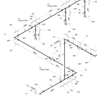
The red lines show the pipe the black dots are the butt welds and A B and C are the dimensions of front to center line and center line to center line.

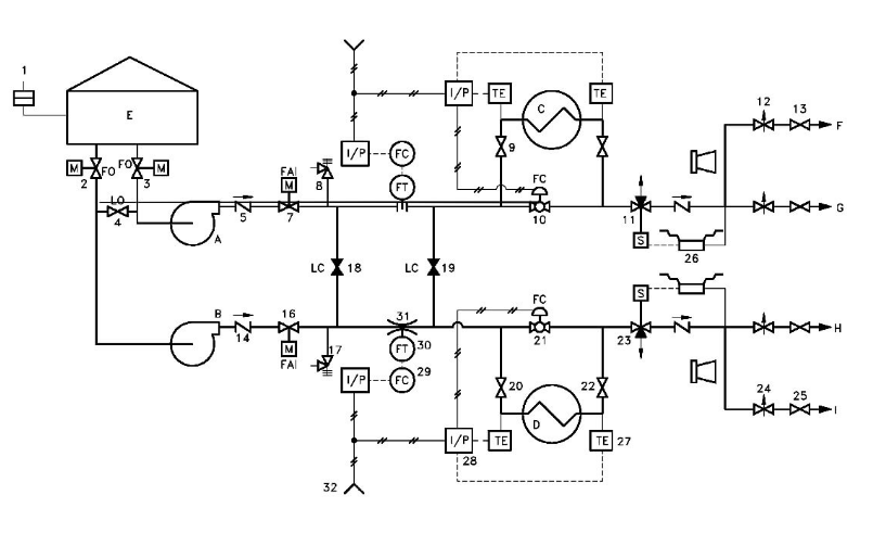
. Clause 30433 of ASME B 313 provides equations to check if any welded piping branch. PID is considered to be the heart of piping they include pipe line-number size material insulationProcess condition physical data operation condition streamflow details Equipment numbers etc. This shall be carried out based on the approved isometricweld map generated from the P ID.
All Main piping items valves fittings etc. ASCII characters only characters found on a standard US keyboard. How To Draw Isometric Piping How Draw Piping Isometric To kwpvenezianotvit Views.
Of these specializations though some of the most highly in-demand hard skills are experience with the software SolidWorks work with electrical systems and work with HVAC. Uses of Reinforcing PAD. Some typical examples of pipes and equipment that are provided with slopes are.
Piping Support Drawings from Pipe Support Standard. The task of an isometric drawing is primarily to show a three-dimensional picture in one drawing. Module 7 is coming soon.
A rough-in plumbing diagram is a sketch for all the plumbing pipes pipe fittings drains and vent piping. Where the pressure is limited by a relieving device the design pressure should not be less than the pressure that will exist in the piping systems when the pressure-relieving device starts to relieve or when the set pressure of the pressure-relieving device. The heat number of the material shall be noted for.
You will Learn the use of your knowledge in practical work by some examples of exercises. Much of a mechanical engineers job is based in being highly technically skilled in a specific area so the exact technical skills a mechanical engineer will need depend on the area of work. For preparation of intermediate MTO construction isometrics nozzle orientation and.
Enter the email address you signed up with and well email you a reset link. Pipe Drafting and Design Roy Parisher and Robert Rhea Gulf Publishing. Download Free PDF View PDF.
Do you have examples of house plans in PDF. Must contain at least 4 different symbols. As you can see this drawing is very simple and quick to implement.
As can be seen there is a fall of 1 mm for every 200 mm of pipe run. This isometric diagram will help determine if all your plumbing meets code. Piping Plan DrawingsGeneral Arrangement Drawings GAD The piping plan or general arrangement drawings Fig.
It is like a picture that lacks artistic details. 1 show all major equipment its northsouth and eastwest orientation and all piping leading to and from equipment are developed by piping designers. 6 to 30 characters long.
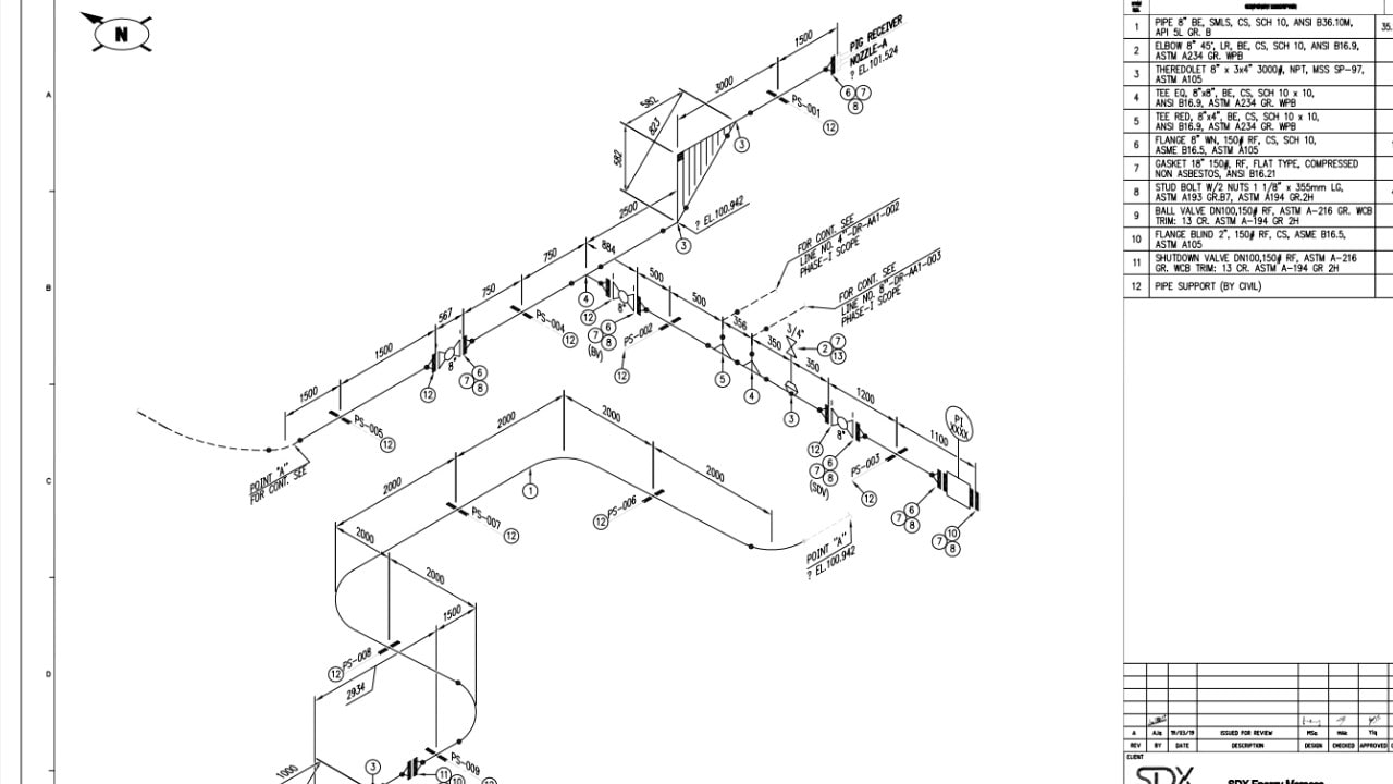
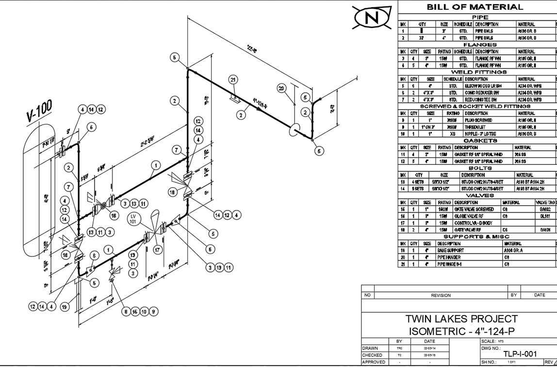
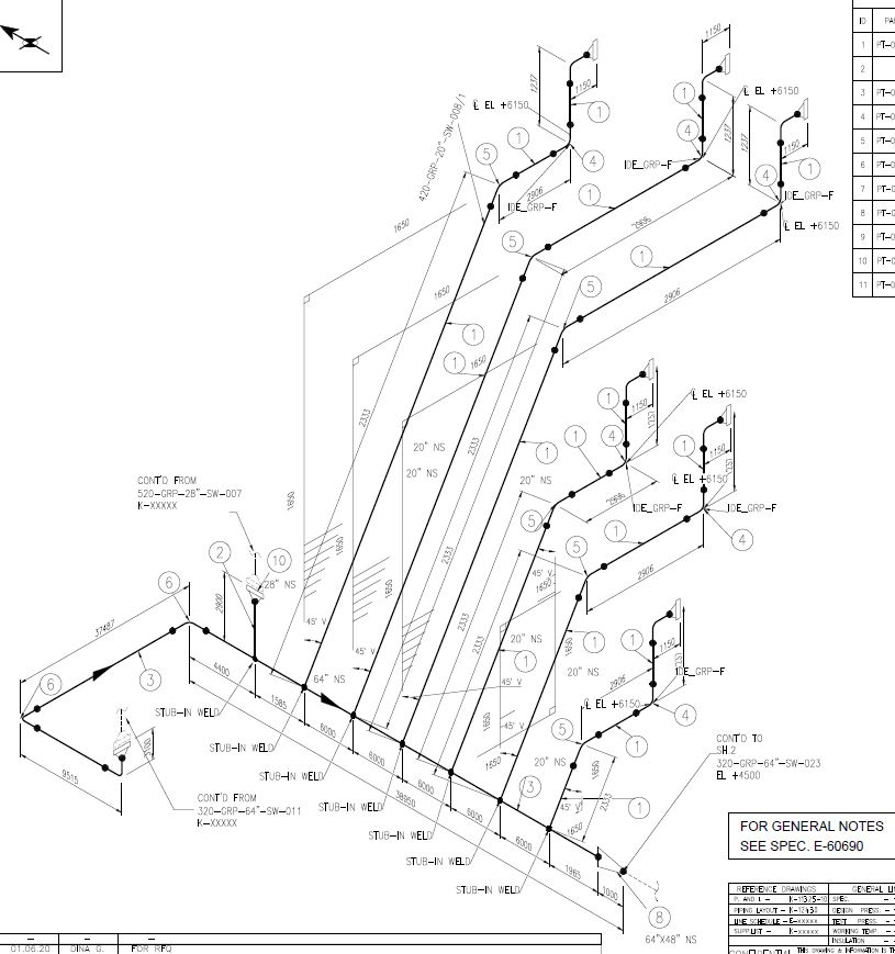
Checking of Piping Isometric Drawings before finally releasing them to the Construction team is very important. In each individual drawing specific items and listed along with approximate quantity. Piping Isometric Drawing Generated From a Corresponding Piping Orthographic Drawing Source.
Design pressure for piping systems should be determined in accordance with ASME B313 with the following additions. Except for clean A4 and A3 drawing sheets and gridgraph paper NO templates pre-prepared pagesdrawing sheets redrawn examples of the site plan etc may be provided to the learners in any form or format. There are many lines inside a complex process industry that have piping slopes.
Those materials are then tabulated in excel or in other company-specific standard forms as per size and quantity involved to make a comprehensive material listing which is sent to the procurement department for purchasing or to the construction team for. Once all details and tagging of support is done you must list out all the required support that going to be need for piping. In the above piping isometric drawing the piping slope is clearly mentioned.
This Course is a perfect combination of theoretical study as well as practical work. Isometric Piping Symbols Library - 18 images - isometric piping and legends in autocad cad kb bibliocad 2d piping symbols library for autocad piping. Most of the design companies involved with isometrics prepare a piping isometric drawing checklist or isometric checklist to help Piping Isometric Checker in their activity.
It minimizes errors and improves quality. Piping Isometric drawings include proportionate drawings with exact dimensions represented line numbers pipe fittings. For finalization of exact piping layouts northeast co-ordinates of match lines which are required for continuation.
When preparing the piping isometric drawing all details including piping material pipe support tag pipe size quantity and materials that would be welded on pipe need to be shown. Checking of Piping Isometric Drawings. It is used to provide the required material from the warehouse to the fabricator for the construction of the piping system as per the isometric drawing.
For reading and understanding a piping isometric drawing one should learn the piping isometric drawing symbols thoroughly. The piping bill of material is not used for purchasing. Used by the piping department.
Besides this course is designed by unique approaches like colors that are used in this course are set according to the level of difficulty of the. BOM is a document used at the site during the construction phase. Piping Inspection is a comprehensive task that is performed following clientcompany-specific inspection documents.
However both of these are weak connections on piping systems and normally limited only for low pressure and temperature applications. Plot Plan Layout Drawing and. Spool number drawing number and sheet with revision shall be checked.
Examples of Piping Slope. By using reinforcing pads it is not required to strengthen the complete header pipe. The isometric view shows the same pipe as in the orthographic view.
AutoCAD Plant 3D can also add 3D models including piping equipment support structures generation of isometric and orthographic drawings. Manual of Engineering Drawing Manual of Engineering Drawing Second edition. Piping Isometric provides the list of BOM for a particular line.
AutoCAD PID software provides a framework for creating schematic piping and instrumentation diagrams that can later be modified and managed in the same program. Many utilities workers have difficulty in clearly visualizing a piping or ducting installation when they are working from a floor plan and an elevation drawing. Table of content Part 1 Part 2 Part 3 Part 4 Part 5 Part 6 Part 7.
Figure 64 shows how a piping iso is generated for one of the lines with line specification 01 2 C30 10 which connects nozzle N1 from vessel V 101 with. Manual Of Engineering Drawing. Purpose of Isometric Drawing.
Usually all these piping and pipeline drawing symbols are constant and does not vary much from one organization to the another. Both types are permitted by many of the international codes and standards including ASME B31. Normally Reinforcing pads are used at stub-on and stub-in branch connections if required per the line list or if required per the branch chart in the piping material specification.
Stub-in and Stub-on are methods for making a fabricated branch connection from the pipe. NO examples of possible or suggested solutions of any component of the PAT may be provided to or procured for the learners in any form.
Piping Iso
Pipe Line Isometric Drawings And P Id Drawings Aqc Inspection

What Is Piping Isometric Drawing How To Read Piping Drawing All About Piping

What Is Piping Isometric Drawing How To Read Piping Drawing All About Piping

Instrumentation Today How To Read An Isometric Piping Drawing
Piping Coordination System Piping Isometrics Isometric Views And Orthographic Views

How To Use Various Rolling Offset Options In Openplant Isometrics Manager Openplant Autoplant Wiki Openplant Autoplant Bentley Communities

Getting Isometric Drawing From Pipe Model Autodesk Community Inventor

Piping Isometrics 2021 Vertex G4plant 2021 Documentation

Pin On Drawings

Piping Guide Basic Design For Piping Isometric Drawings
Piping Isometric Drawings
P Id Isometric 2d Piping Plans Procad Software

An Example Isometric Drawing Showing A Single Spool Its Associated Download Scientific Diagram

Isometric Pipe Drawing Download

Isometric Pipe Drawing Pdf Download
How To Set Branch Pipes For Isometric Drawings Be Shown Uniformly In Autocad Plant 3d Autocad Plant 3d Autodesk Knowledge Network

How To Read Basic Piping Isometric Drawings Piping Analysis Youtube

Piping Isometric An Overview Sciencedirect Topics